
 Enquire now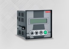
Select image to view the original
OPERATING MANUAL
Intelligent Motor Protection Relay — i.MWM 4 TO 61 A
Current range
0.25 TO 5 Amp4 TO 61 Amp40 TO 500 Amp400 TO 1200 Amp
Operating instructions for this model and current range. Refer to the original document for installation, settings, and operation.
 Enquire about this model
The specifications list multiple current ranges. The operating manual below applies to i.MWM 4–61 A.
View operating manuali.MWM · 4 to 61 ATECHNICAL INFORMATION
Know your product.
Features
| Display | Current, Voltage, P.F, KW, KWh Operating Hour, Start Counter Trip Counter, Current & Voltage Status at Last Trip through 16 X 2 LCD. |
|---|---|
| Power Source | Three Phase Four Wire(R-Y-B-N) |
| CT Type | In-built for 0.25 TO 5 Amp External for all other Current Ranges |
Protections
- Single Phasing Protection (C)
- Single Phasing Protection (V)
- Over Load Protection
- Over Voltage Protection
- Under Load Protection
- Under Voltage Protection
- Phase Un-balance
- Phase Reversal Protection
- Locked Rotor Protection
- Short Circuit Protection
- Earth Fault Protection
Mounting
| Device | Door Mount (92 X 92 mm) |
|---|---|
| External CT Unit | DIN Rail Mount For 4 TO 61 Amp |
| External Phase CTs | Cable / BUS BAR mount For 40 TO 500 Amp & above With Selectable IT Curve OR Definite Time With Selectable Trip Time for SPP & UL With Selectable Rotor Locked Value With RS-485 Communication |
| Optional | Add On Current Module For Remote Monitoring of Current. 4 to 20mA O/P w.r.t. Runnung KW value |
EXPLORE THE RANGE